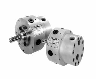
The Jahns radial piston motors series HMF, HMT, HMs and HMw come along with fixed displacements. Speed is dependent on the fed flow and torque by the applied pressure. The motors could be combined with hydraulic ventilated brakes and/or planetary gear reducers.
The cylinders (5 or 7) are starlike arranged around the drive shaft. The displacement is a product of the number of pistons, the piston area and the excentricity of the driving shaft. With radial piston motors high volumentric and mechanical efficiencies could be achieved.
HMs:
8 motors in 4 sizes are available as standard with a range of displacement volumes between 1 in3/rev. to 9 in3/rev. All motors come with a keyed shaft or splined hollow shaft. Continuous operating pressure: 3,045 to 4,060 psi.
HMw:
18 motors in 6 sizes are available as standard with a range of displacement volumes between 11 in3/rev. to 384 in3/rev. All motors come with the option of a keyed shaft, splined shaft or splined hollow shaft. Options include contact free revolution counter, hydraulically applied multi-disc brakes, valve block with integrated pressure relief and pre-fill valves. Continuous operating pressure: 3,045 to 4,060 psi.
HMF and HMT:
This new HMF product series comes in 7 sizes with the possibility of 55 different displacement volumes between 2 in3/ rev. to 262 in3/ rev. Manufactured in large batch production means that this product range of motors is competitively priced. Continuous operating pressure: 3,625 psi and max pressure to 6,090 psi. Available with different shaft configurations and revolution counter. The HMT series has higher revolution speed.
HMZ:
The HMZ radial piston motor comes in 2 sizes with smooth and step-less transmission. The ratio of minimum to maximum displacement volumes is between 1:2 and 1:4.
Jahns is a supplier and hydraulic motor manufacturer for various applications including construction, mechanical, marine, and industrial.
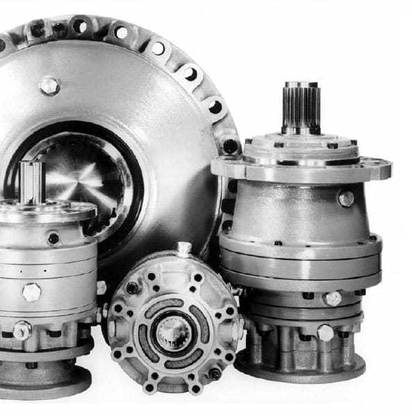
Coaxial planetary gear drive units are available in 16 different sizes up to 221,,268 ft/lbs. (300,000 Nm), and Angle drive planetary gear drives available in 15 sizes up to 110,600 ft/lbs. (150,000 Nm). Available with different shaft configurations.
On the input side the gear units can be supplied with keyed shaft for belt transmission, with hydraulically applied multiple disc brakes, as well as connections for all currently available hydraulic and electric motors. For the main drive side, splined hubs, mounting flange, main drive flanges, pinions, splined shafts and shrink discs are also available
Jahns is a supplier and hydraulic motor manufacturer for various applications including construction, mechanical, marine, and industrial.
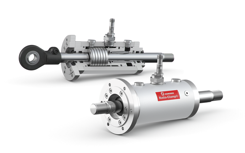
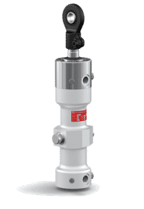
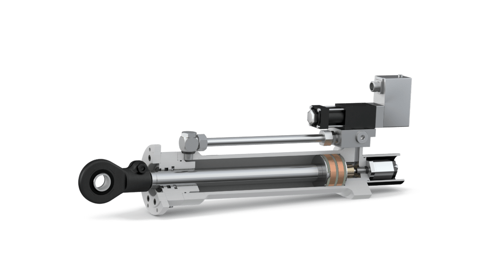
The Hänchen Ratio-Clamp® keeps the position for you. This device is a positive rod clamping safety device. The Ratio-Clamp is unlocked by hydraulic pressure. In the event of an electrical/hydraulic power loss, the potential energy of the internal Bellville washers load a conical piston, driving it over the friction fingers resulting in securing the load. “A true self contained safety clamp.”
Wherever power failures or malfunctions pose a risk to the safety of people or machinery, the rod locking device is there to save the day. It is also useful to accurately hold the cylinder rod in an exact position without the need to keep hydraulic pressure on the cylinder, thereby saving energy while maintaining accuracy. It clamps down and fixes the piston rod right where it is with no additional power needed.
Guaranteed advantages of hydraulic rod locks
No axial rod movement during clamping and releasing
Protective clamping effect in case of a power failure
Load capacity that is independent of direction
Clamps completely surrounding rods
IoT 4.0 Compatible: Integrated sensors to know if the clamp is locked or unlocked
Boasting a retention force of up to 101,000 lbf., the clamp hydraulically holds the piston rod in whatever position it is in at that particular moment without having to generate extra power (no extra energy) for an unlimited period of time. The clamping device Ratio-Clamp is approved by the German Technical Inspection Agency (TÜV).
Special development of Custom solutions (larger rod diameters, intermediate size, greater clamping forces) pose no problem for the Hänchen specialists. Hänchen is particularly proud of its RC-H model. Following a request from the Health and Safety Centre of the Employers’ Liability Association (BGZ iron and metal section III, Düsseldorf), Hänchen developed the new safety clamping hydraulic Ratio-Clamp under extreme conditions for use with hydraulic presses and injection molding machines.
Ratio-Clamp Applications
Testing technology in aviation: The setups for aviation tests have been refined to the last detail. Cylinders are used in different fields of testing, simulating ambient conditions and loads during different flight phases. The Ratio-Clamp® is used to protect the intricately constructed and expensive systems.
Production in molding and injection presses: Clamping units ensure safety during the pressing process in molding and injection presses for the production of synthetic and rubber molder parts in accordance with EN 289.
Maintenance in railway technology: During maintenance, trains must be fixed in a raised state. The Ratio-Clamp® is ideally suited for this purpose, as it holds the train securely in position until the work had been completed.
Production in grinding machines: During the production process of ICE rail sleepers, extremely large and heavy concrete workpieces must be positioned for grinding safely and with an accuracy of 0.01 mm. Hänchen’s hydraulic cylinders and Ratio- Clamp® clamping units are designed exactly for these requirements.
Production in profilling machines: Hänchen clamping units ensure precise machining and consistent quality in the production of metal profiles. During the production process, they facilitate the machining of the profiles by locking the forming tools in place. Ecological and efficient, purely with spring power.
Hänchen is a supplier and hydraulic cylinder manufacturer for various applications including construction, mechanical, technological, and industrial.
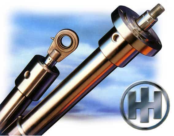
Everyone who has heard of Hänchen is aware that its worldwide reputation is based on hydraulic cylinder solutions that are anything but standardized. The standardization actually deals with nothing more than basic dimensions and connections, mounting, parts, etc. Indeed for the common solution, a standard cylinder will often do the job without any problems. In many demanding applications it is possible to use a standard Hänchen cylinder due to the high quality levels they attain. In principle, they make exclusive use of honed cylinder tubes for all their cylinders. Hänchen also guarantees that all the cylinders in its product range, as well as normalized cylinders, comply with the most exacting of geometrical accuracies. Hans Holland Hydraulik offers a standard range with particularly cost-effective solutions. Whether you require newly-manufactured components or the additional machining of existing items, you can be sure their production facilities will meet your individual needs. Hans Holland Hydraulik also offers you preservation and color treatments. Also short delivery times, even of large batches of items, are no problem. Their standard cylinders often require only simple modifications to fulfill a wide range of applications, without the greater expense of full customization.
Hänchen is a supplier and hydraulic cylinder manufacturer for various applications including construction, mechanical, technological, and industrial.
Specialty cylinders are offered by Hänchen. Hänchen has renown for top quality hydraulic cylinders for many years with one of the largest testing range in the market, offering lightweight servo actuators for static applications or high frequency cylinders for dynamic testing:
Advantages at a Glance:
Single or double-rod cylinders
Up to 320 bar/4,600 psi
Modular system for efficient change of applications
Integrated position transduced, per your specifications
Optional mounting plate for control valve
Optimal price-performance ratio
Servo valve, sensor, and control software agnostic – we work with all brands
Easy serviceability and spare parts available
Which series is right for my application?
Servo cylinders of the Series 120 and 300 are light-duty test actuators for simple testing tasks. For more challenging tasks, the Series 320 is a hydrostatic design offering excellent precision and high performance, allowing for high lateral forces and speeds.
General Specifications:
Bore, mm (in): 25-200 (0.98-7.87)
Force, kN (lbf): up to 1,568 (up to 352.5)
Stroke, mm (in): 1-1,500 (0.04-59.06)
Frequency (Hz): up to 100+, limited by servo valve
The 320 Series: Constructed for highly dynamic tests
Perfect for industrial applications, structure tests, and load simulations: the Series 320 test cylinder is the best choice for challenging tasks. It performs well, for example, in checking the functional safety of systems, component parts, or products; for structural testing of airplanes, refrigeration compressors, automobile exhaust system; or for simulating loads and movement, such as operational profiles and flight profiles.
The Series 320 is built from a solid block of steel. This means that any part of the cylinder can be customized to your requirements unlike standard models with limited sizing options. Rigid construction of the cylinder means means no leakage, a long service life, and good data.
4 Stand Out Features of the 320 Series:
Bores adjustable to the millimeter: The working areas can be designed individually for the respective requirements, saving acquisition and operating costs for the required periphery, and increasing energy efficiency.
Protection against unforeseen movement: Emergency cushion adds protection for the cylinder and test specimen. This is included in the stroke as standard. The effective stroke is between the two emergency cushioning.
Operation without a leak oil pump: Thanks to elaborate sealing and guiding system, cylinders don’t need leak oil pumps. The cylinders are equipped with high-quality bronze coatings for optimum emergency running properties.
Modular system efficient change of applications: Mounting parts and accessories fit cylinders with different forces and do not have to be purchased several times for one test field.
Hänchen is a supplier and hydraulic cylinder manufacturer for various applications including construction, mechanical, technological, and industrial.
Stick-Slip in Hydraulic Cylinders
Our Hydrostatic Design
How are Test Cylinders Used?
Automotive
Servo hydraulic lifecycle tests are the current industry standard for automobile components that are used far beyond safety-related structural elements. Users can depend on hydraulic test actuators for high positioning accuracy and reliability in applications for test systems and real time control. A test cylinder with a dynamic lift of up to 35 mm (1.3 in.), speed of 1.3 m/s (51.2 in/s), and acceleration of up to 50 m/s (1968.5 in/s) could be used for a test load requiring up to 28 kN (6,294 lbf) and a frequency up to 20 Hz.
Aerospace
System tests that simulate loads and environmental conditions in different flight phases are particularly demanding. To test the landing flaps and slats, servo hydraulic cylinders could be used here to replicate the airflow that involves rapidly changing forces with irregular parameters. For example, a servo cylinder with a bore between 40 to 160 mm (1.5 to 6.2 in.) could be used for a test stand with a holding force between 140 – 300 kN (31.4 to 67.4 lbf) and a stroke requirement of 300 to 1,670 mm (11.8 to 65.7 in.).
Fluid Power
To determine the characteristic values of a seal, seal test benches are suitable for simulating a wide range of operating conditions. Double rod cylinders could be used here for fatigue tests focused on examining the frictional force of the seals, tightness on rods and shafts.
Choosing a Testing Cylinder
Dynamic Movement
First, determine if the cylinder will be used in highly dynamic applications, such as torque/torsion testing of axial loads and other drive line components. If so, seal protection is important to have, along with a servo valve that can be mounted to the actuator to offer more control to the device. It is important to know the application including the speed, pressure, loads, and any forces acting on the cylinder.
Frequency
What frequency will your cylinder require? Industrial applications and dynamic testing typically have higher frequency ranges, with some frequencies greater than 100 Hz.
Seals
It’s important to pay attention to the conditions your cylinder will be in. Conducting tests in conditions like salt spray fog, in climate chambers, or in a lab require individualized protection. Seal factors to pay attention to include temperature ranges, types of movement (simple, sensitive, controlled), outdoor stress, stick resistance, and type of medium, etc.
Load Holding
If loads need to be held in position for extended times, a rod lock can be included which allows a load to be held in a precise position and without power/pressure being applied.
In addition to their standard cylinder range, custom cylinders are offered by both Hans Holland and Hänchen. IC-Fluid Power also has other sources to make any cylinder you can imagine. Simple or complex, large or small bore, long or short length, fast or slow…the possibilities are endless. Our engineers are available to help with your specialty cylinder application. Contact us today for more information.
Hans Holland and Hänchen are suppliers and custom cylinder manufacturers for various applications including construction, mechanical, marine, and industrial.
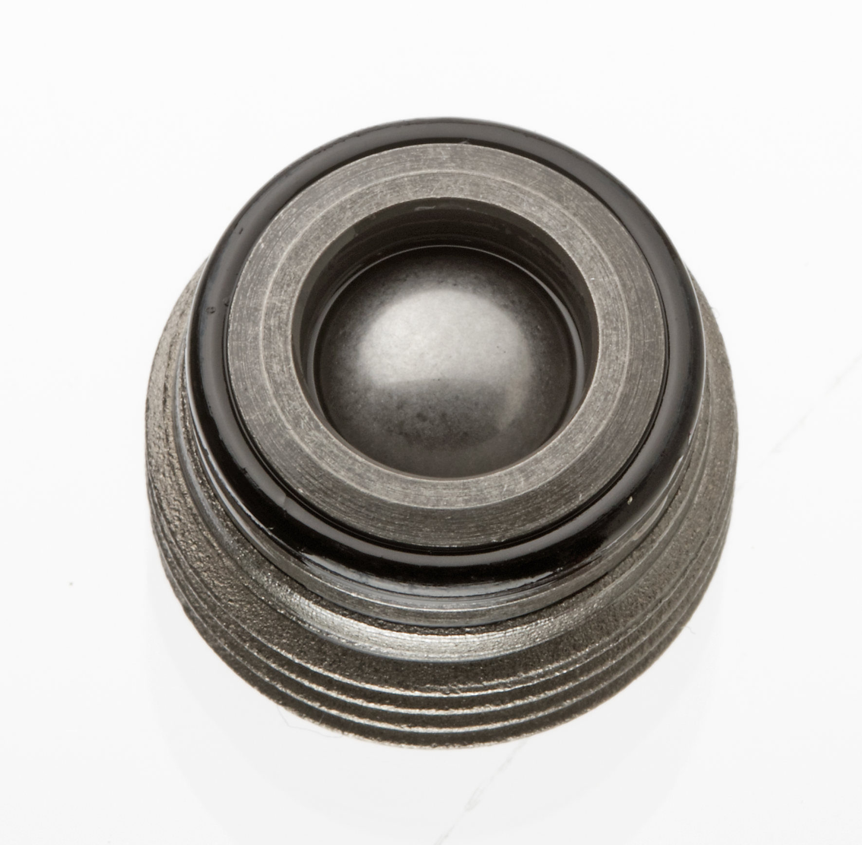
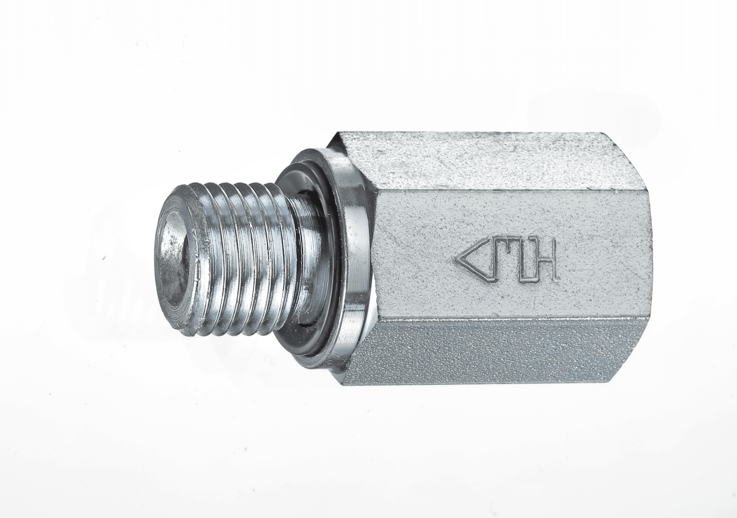
Check valves block an oil flow in one direction and allow it in the other direction. They are a type of shutoff valve. The check valve is inserted when an oil flow shall be allowed in one direction only. Meanwhile, the usage of check valves prevents backflow of the fluid.
Advantages at a Glance:
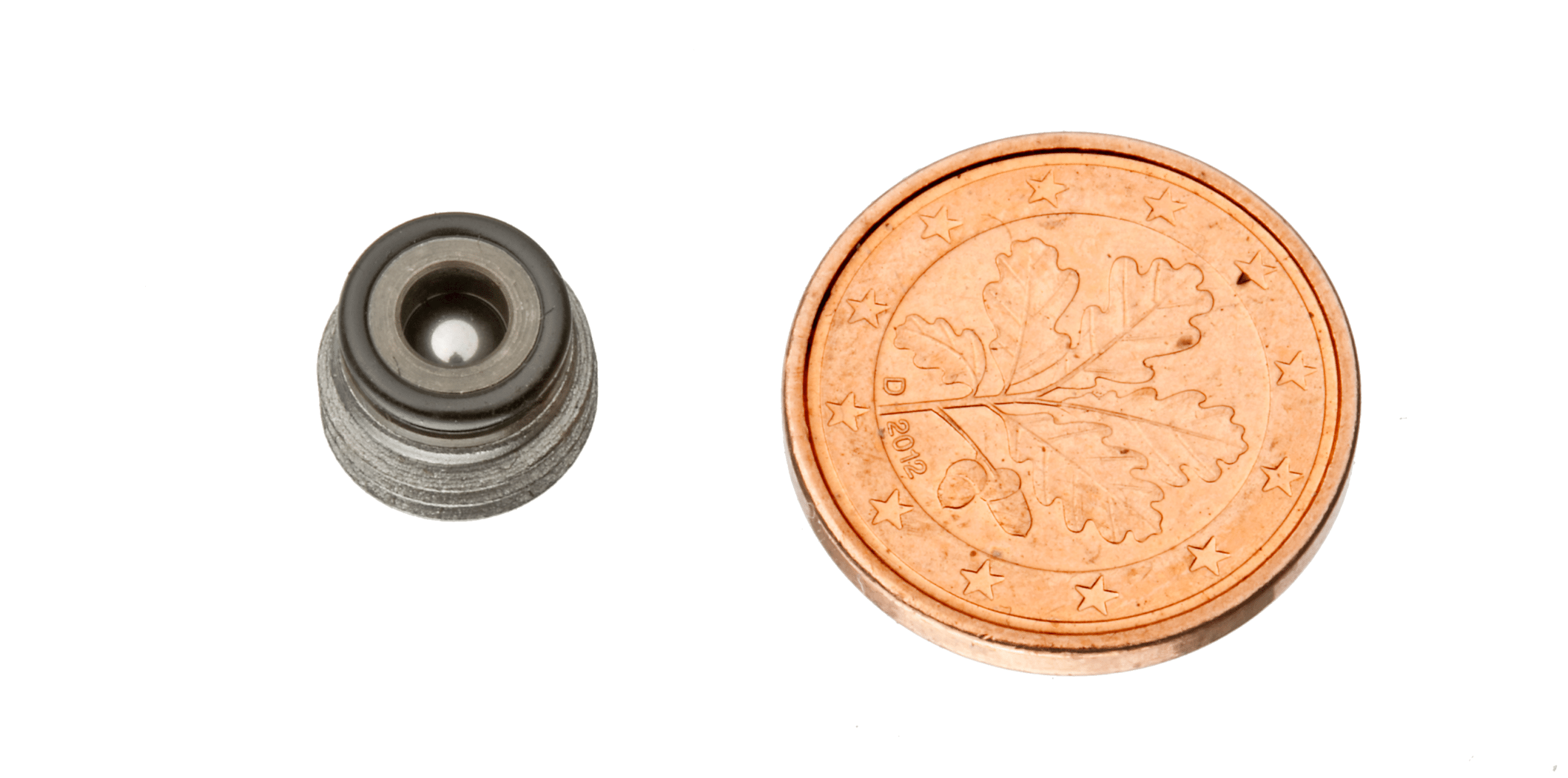
Spherical shell
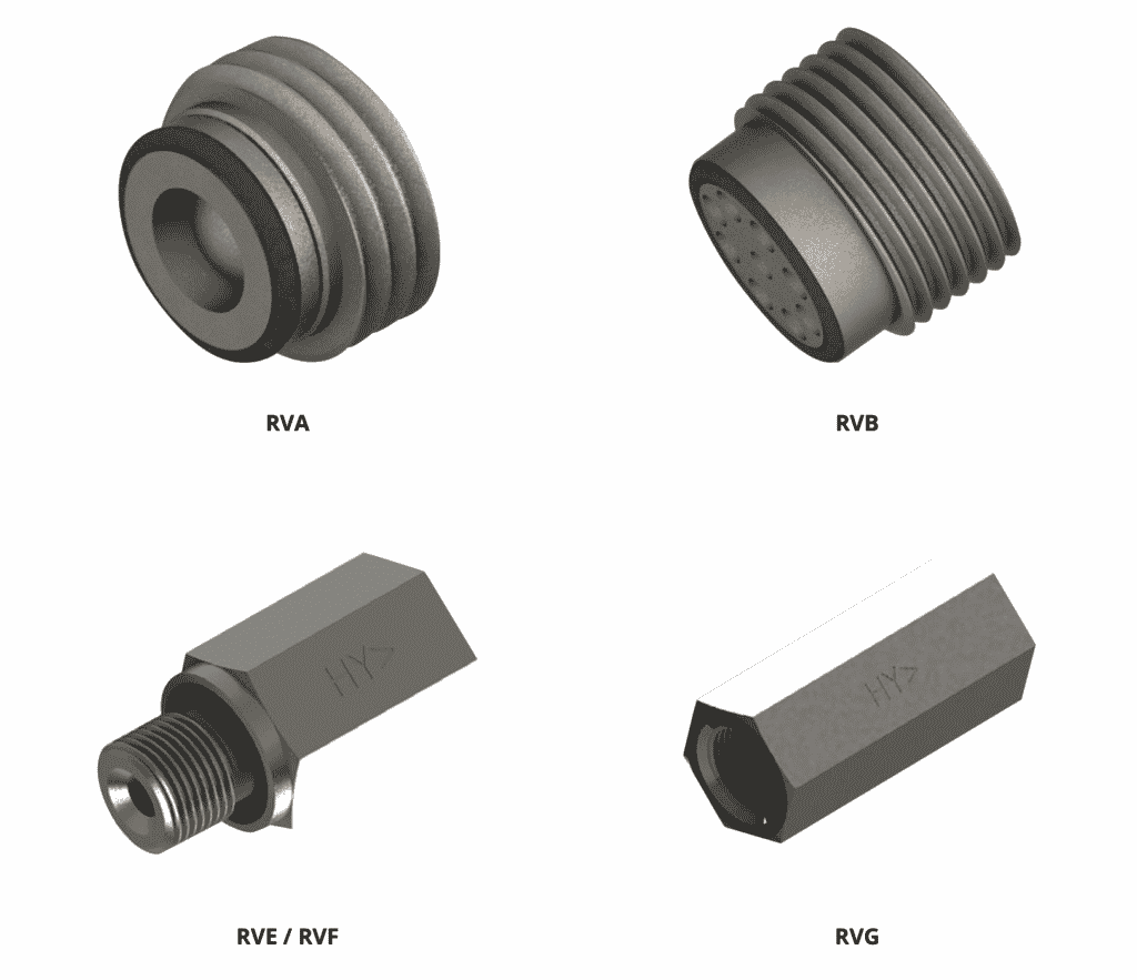
Available as screw-in or caged version
Nominal size 1/16 – 1/8 – 1/4 – 3/8 – 1/2 – 3/4
Working pressure 10,000 psi
BSP or metric thread
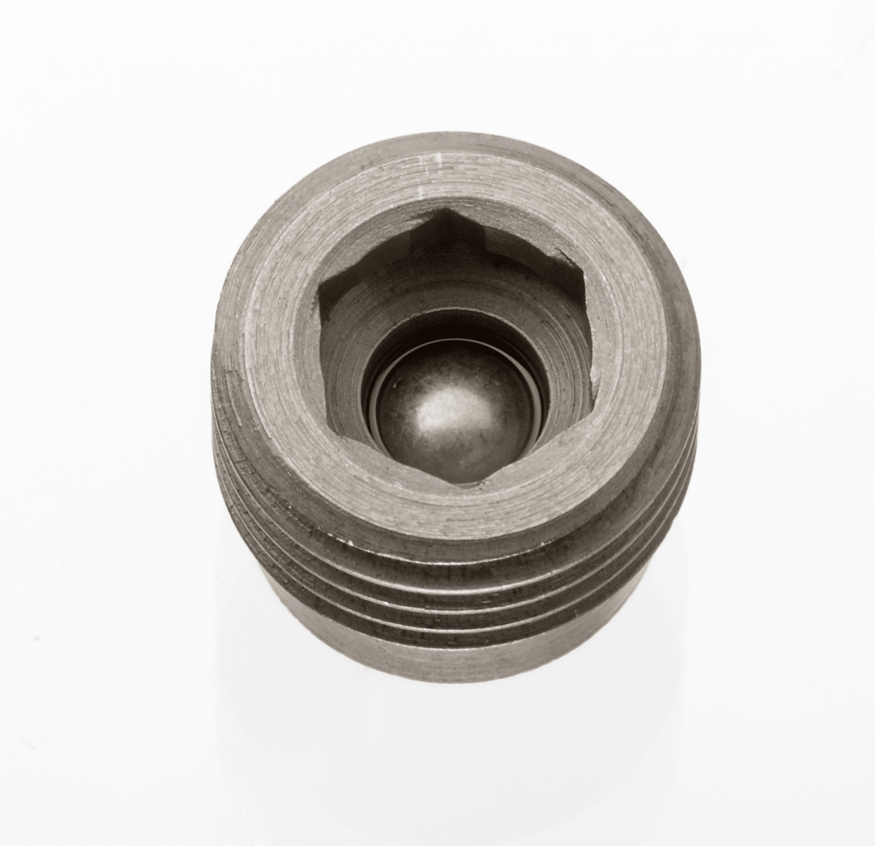
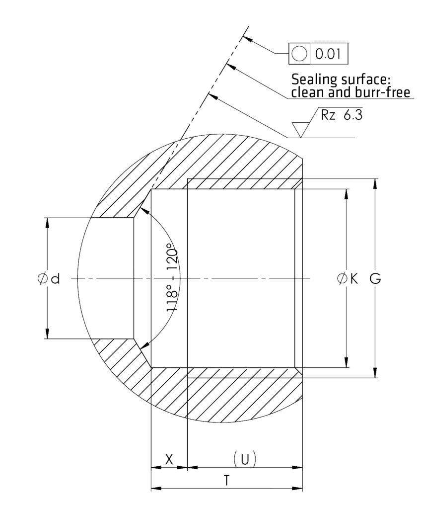
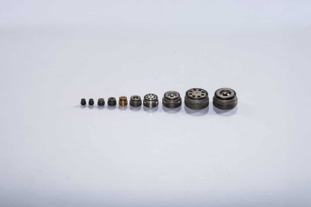
The HYTORC-check valves are available with a screw-in or caged design. Even so, both designs can be obtained in two flow directions: with the screw-in direction closed or with free-flow. The spherical cap remains reliably tight in every position, in case of multiple switching cycles and under severe stress.
The HYTORC check valve easily screws into a regular hole (Dimensions screw-in drill). The screw-in check valves are sealed through an edge sealing which is turned to the cage. The edge sealing, together with the drill draft, forms a gap-free chamber for the O-Ring. The gap-free chamber and the O-Ring are repeatable sealing.
The valve is made of a high-strength hardened steel. Moreover, the ball seat is specially treated and the spherical shell is manufactured with a high tensile hardened and polished ball bearing ball. Thus, the design of the check valves is compact and economical which saves space and offers simple installation.
Technical Data
Permissible Operating Pressure
up to 10,000 psi (700 bar) (lock pressure)
Permissible Temperature
–40 to +176 °F (–40º +80°C)
Viscosity
5–500 cSt
Installation Position
any
Material
Body: normal and stainless Steel Gasket: NBR rubber
Screw-In Check Valve
Order No.
Type
G
L
a
n
z x d
o-ring
12 011 102
RVA 2-M
M 6
6
3.4
3.4
4 x 1.2
2.5 x 1
12 011 103
RVA 3-M
M 8×1
6
3.3
4.7
6 x 1.6
4 x 1
12 011 104
RVA 4 (RVA 4-M)
G 1/8 M 10×1
6.7
3.5
6
6 x 1.8
6 x 1
12 011 106
RVA 6 (RVA 6-M)
G 1/4 M 14×1.5
8.2
4.8
8.9
8 x 2.15
9 x 1
12 011 108
RVA 8 (RVA 8-M)
G 3/8 M 18×1.5
10.1
5.6
10.8
8 x 3.2
11 x 1.5
12 011 110
RVA 10 (RVA 10-M)
G 1/2 M 22×1.5
11.6
6.8
14 (14.5)
8 x 3.8
14 x 1.5
12 011 116
RVA 16 (RVA 16-M)
G 3/4 M 27×2
14.2
7.8
18.5
8 x 4.6
18.77 x 1.78
Screw-In Drill
Type
G
K
d [max]
T [min]
U
X [max]
RVA 2-M
M 6
5H11
2
6
4.2
1.8
RVA 3-M
M 8×1
7H11
3.5
5.9
4.1
1.8
RVA 4 (RVA 4-M)
G 1/8 M 10×1
8.8H11 (9H11)
5
6.5
4.3
2.2
RVA 6 (RVA 6-M)
G 1/4 M 14×1.5
11.8H11 (12.5H11)
8
8
5.8
2.2
RVA 8 (RVA 8-M)
G 3/8 M 18×1.5
15.25H11 (16.5H11)
10
9.3
6.7
2.6
RVA 10 (RVA 10-M)
G 1/2 M 22×1.5
19H11 (20.5H11)
12
10.5
8
2.5
RVA 16 (RVA 16-M)
G 3/4 M 27×2
24.5H11 (25H11)
16
13
8.7
4.3
RVA Opening Pressure + Starting Torque
NG
2
3
4
6
8
10
16
Opening Pressure
bar
0.36
0.26
0.17
0.19
0.22
0.18
0.17
Starting Torque
Nm
6
8
12
20
25
40
80
Screw-In Check Valve
Order No.
Type
G
L
a
AF
o-ring
12 011 202
RVB 2-M
M 6
6.3
3.3
3
2.5 x 1
12 011 203
RVB 3-M
M 8×1
6.6
3.6
4
4 x 1
12 011 204
RVB 4 (RVB 4-M)
G 1/8 M 10×1
7.7
4.6
5
6 x 1
12 011 206
RVB 6 (RVB 6-M)
G 1/4 M 14×1.5
10
6.6
7
9 x 1
12 011 208
RVB 8 (RVB 8-M)
G 3/8 M 18×1.5
11.4
7.5
8
11 x 1.5
12 011 210
RVB 10 (RVB 10-M)
G 1/2 M 22×1.5
13.1
8
10
14 x 1.5
12 011 216
RVB 16 (RVB 16-M)
G 3/4 M 27×2
16.9
10.7
12
18.77 x 1.78
Screw-In Drill
Type
G
K
d [max]
T [min]
U
X [max]
RVA 2-M
M 6
5H11
2
6.7
4.2
2.2
RVA 3-M
M 8×1
7H11
3.5
6.5
4.4
2.1
RVA 4 (RVA 4-M)
G 1/8 M 10×1
8.8H11 (9H11)
5
7.5
5.3
2.2
RVA 6 (RVA 6-M)
G 1/4 M 14×1.5
11.8H11 (12.5H11)
8
10
7.6
2.4
RVA 8 (RVA 8-M)
G 3/8 M 18×1.5
15.25H11 (16.5H11)
10
10.9
8.6
2.3
RVA 10 (RVA 10-M)
G 1/2 M 22×1.5
19H11 (20.5H11)
12
12
9.1
2.9
RVA 16 (RVA 16-M)
G 3/4 M 27×2
24.5H11 (25H11)
16
15.5
11.5
4
RVB Opening Pressure and Starting Torque
NG
2
3
4
6
8
10
16
Opening Pressure
bar
0.77
0.47
0.22
0.22
0.2
0.23
0.2
Starting Torque
Nm
6
8
12
20
25
40
80
RVE Screw-In Socket with Elastic Sealing
Order No.
Type
G
L
t
O
AF
12 011 306
RVE 6
G 1/4
40
12
2.5
19
12 011 308
RVE 8
G 3/8
42
12
2.5
22
12 011 310
RVE 10
G 1/2
51
14
3
27
RVF Screw-In Socket with Elastic Sealing
Order No.
Type
G
L
t
O
AF
12 011 406
RVF 6
G 1/4
40
12
2.5
19
12 011 408
RVF 8
G 3/8
42
12
2.5
22
12 011 410
RVF 10
G 1/2
51
14
3
27
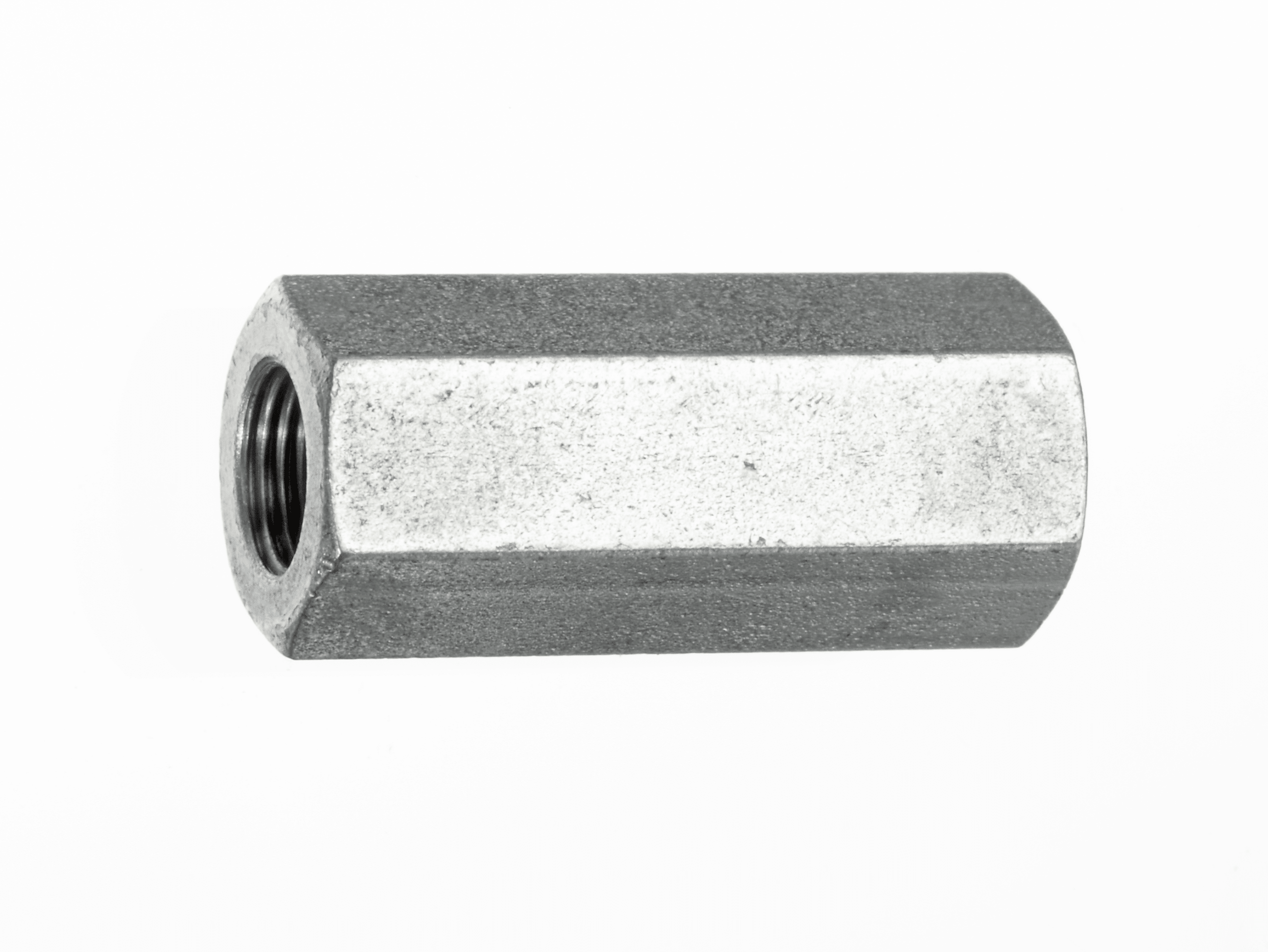
RVG Internal Thread on Both Sides
Order No.
Type
G
L
t
AF
12 011 506
RVG 6
G 1/4
45
12
19
12 011 508
RVG 8
G 3/8
48
12
22
12 011 510
RVG 10
G 1/2
58
14
27
RVA, RVE, RVG Flow Rate
Curve
Q Max l/min
1
=RVA2
3
2
=RVA3
6
3
=RVA4 – RVE4 – RVG4
10
4
=RVA6 – RVE6 – RVG6
25
5
=RVA8 – RVE8 – RVG8
45
6
=RVA10 – RVE10 – RVG10
70
7
=RVA16 – RVE16 – RVG16
100
RVB, RVF Flow Rate
Curve
Q Max l/min
8
=RVB2
2
9
=RVB3
4
10
=RVB4 – RVF4
8
11
=RVB6 – RVF6
18
12
=RVB8 – RVF8
30
13
=RVB10 – RVF10
60
14
=RVB16 – RVF16
90
Fitting Tools
Order No.
Desc.
for Type
b
zxd
c max
AF
9 05855 00
RMS 2
RVA 2
3.3
4×1
2
4
9 05855 00
RMS 3
RVA 3
4.7
3×1.5
1.9
8
9 05855 00
RMS 4
RVA 4
6
3×1.5
2.4
10
9 05855 00
RMS 6
RVA 6
8.9
4×2
2.7
12
9 05855 00
RMS 8
RVA 8
10.8
4×3
3.8
17
9 05855 00
RMS 10
RVA 10
14.5
4×3
4.5
19
9 05855 00
RMS 16
RVA 16
18.6
4×4
5.2
27
Hytorc-HydroWer is a supplier and power unit accessory and valve manufacturer for various applications including construction, mechanical, marine, and industrial.
A compact alternative to a ball valve, butterfly valves (or shut-off valves) are low-pressure valves used on hydraulic reservoirs so there is no need for draining during maintenance.
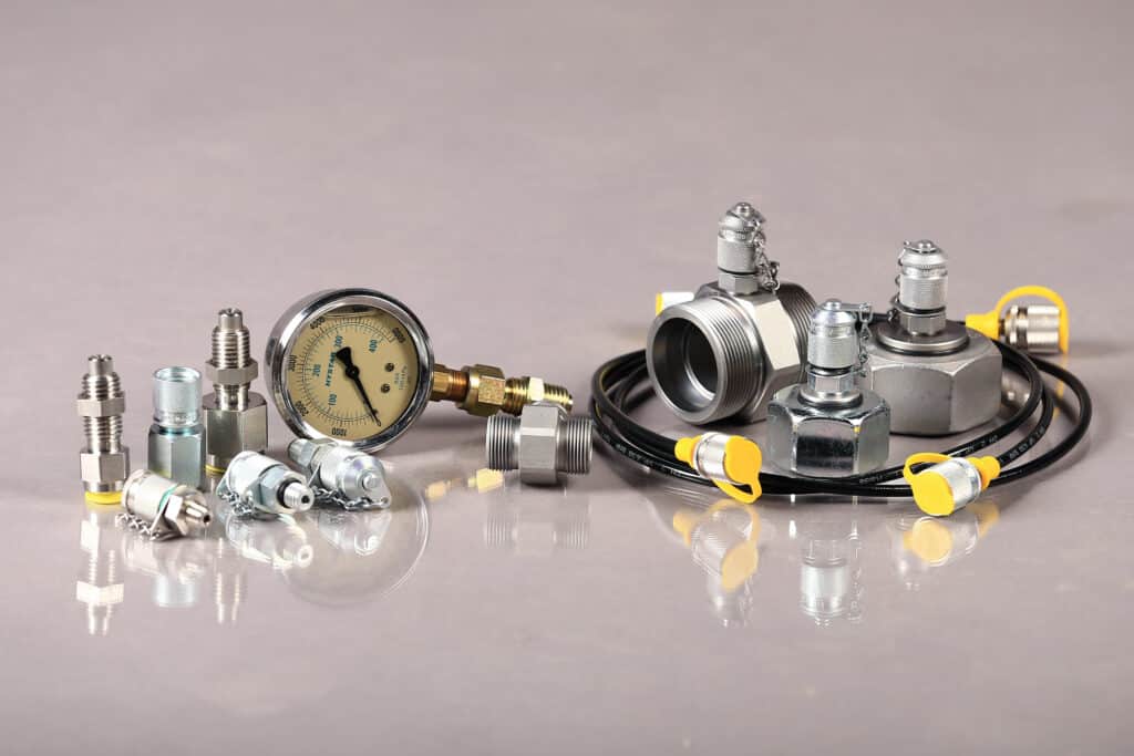
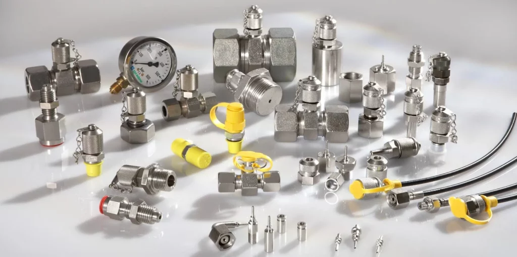
Pressure is one of the most important diagnostic parameters in the hydraulic circuit. Obtaining pressure readings is essential to successful preventive maintenance and troubleshooting. The Spradow test points allow the connection of a pressure gauge in only seconds while the equipment is running. It is the safest, cleanest and most convenient way of measuring pressure. Designing your equipment with the Spradow test points will improve the quality of your equipment and in today’s market, higher quality makes the equipment more attractive to potential buyers. The spring loaded check valve inside the test point opens during engagement of the special micro-bore hose fitting end. The connection can be performed under pressure without the use of tools. A single gauge connected to the high pressure micro-bore hose can check an unlimited number of test points. We also offer various types of hose assemblies for direct connection to the test fitting.
Spradow is a supplier and test point and test hose assembly manufacturer for various applications including construction, mechanical, technological, and industrial.
A compact alternative to a ball valve, butterfly valves (or shut-off valves) are low-pressure valves used on hydraulic reservoirs so there is no need for draining during maintenance.
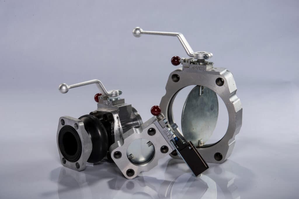
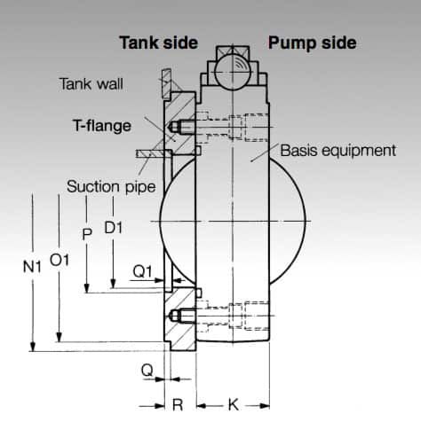
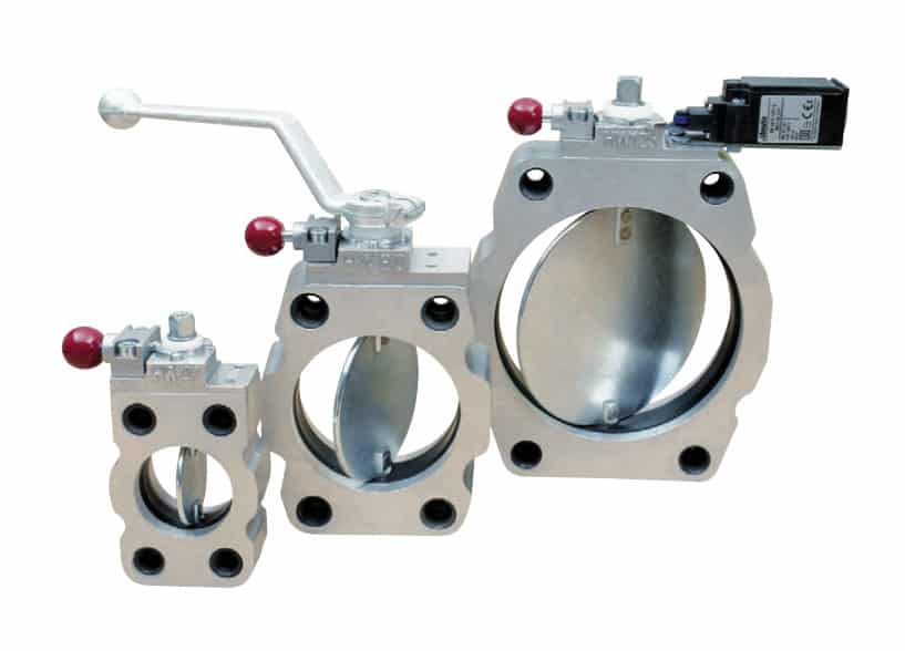
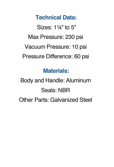
The Hytorc butterfly valve is a component designed to save time for the technician working on the hydraulic system by not having to drain the reservoir. The valve is designed for low pressure hydraulic lines up to 230 psi and can be installed into the pump suction line or mounted directly on to the hydraulic reservoir for example. The maximum pressure differential on either side of the valve should not exceed 58 psi when the valve is closed.
Standard Specifications:
Handle/Shifter: Equipped with a shifter for manual actuation
Material: Aluminum body and handle; other parts made from galvanized steel
Temperature: For environments ranging from -4°F to 176°F
Seals: Fitted with NBR seals for optimal sealing performance
Hydraulic Butterfly Valves Features:
Thin profile and SAE flange for easy design into hydraulic circuits
Ideal for space limited mobile applications
28% more oil volume than ball valves
Simple maintenance; no reservoir draining
Easy installation for improved efficiency
Designed for low-pressure suction lines only
Automatic locking mechanism
Optional limit switch
Aluminum body for reduced weight
Low cost for large pipes
Options: reservoir flange, limit switch, and threaded adapter brushing inserts
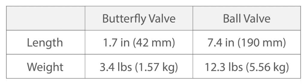
Comparing Size: Butterfly Valve versus Ball Valve on 4″ Pipe
For a 4″ pipe, butterfly valves are nearly 77% shorter and 71% lighter than a ball valve of the same diameter.
Ultra-compact profile to minimize space requirement:
In applications where fitting ball valves into the design poses a challenge, butterfly valves provide an effective solution. These valves are significantly shorter and lighter than their counterparts, facilitating easier handling and installation. The advantages of this design become increasingly evident as the nominal diameter rises. This is particularly beneficial in mobile hydraulics where space is a premium.
Convenient, simplified maintenance:
Thanks to internal clamping bolts, the valve is tightly secured to the reservoir even when even when disconnecting pipes or flexible connectors. This design enables maintenance without draining the reservoir.
Easy installation:
Shut off valves can be fitted between flanges due to the lateral recesses. Alternatively, heavy suction pipes can be held with additional screws.
No loss of oil volume:
The valve’s inner diameter is larger than the pipe, enabling full flow capacity without compromising on oil volume. This feature is crucial for maintaining efficient and precise control.
Automatic locking mechanism:
The self-engaging lock bar provides a secure and stable connection. The lock bar automatically engages in all switch positions; fully open, closed, or at an intermediate position, and ensures arresting of the valve’s position even without a shift lever.
Limit switch for preventative measures:
Prevent damage to your pump by making sure the valve is open prior to turning on the pump.
Hytorc-HydroWer is a supplier and power unit accessory and valve manufacturer for various applications including construction, mechanical, marine, and industrial.
A compact alternative to a ball valve, butterfly valves (or shut-off valves) are low-pressure valves used on hydraulic reservoirs so there is no need for draining during maintenance.
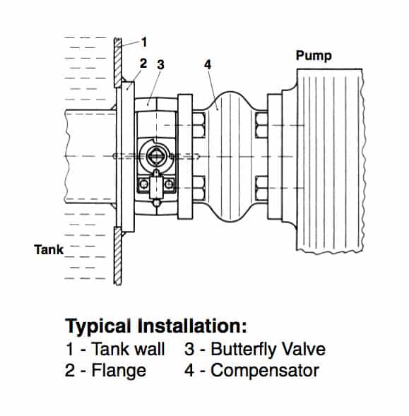
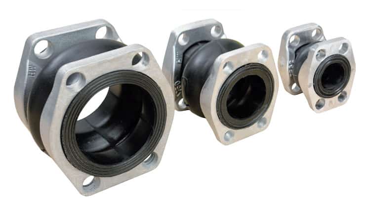
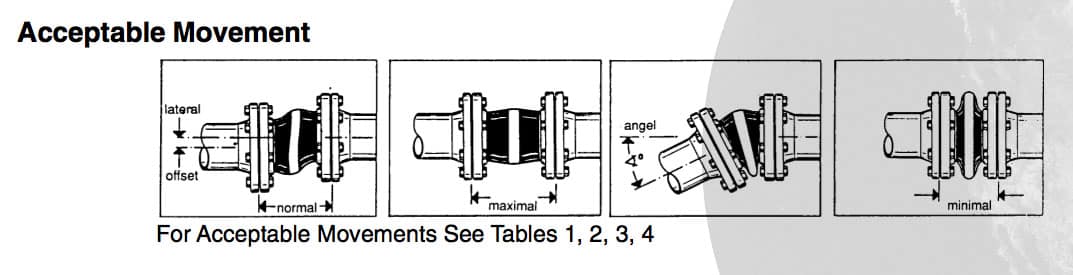
The HydroWer Rubber Compensator is a product that qualifies as one of the best kept secrets of power unit accessories. The compensators are flexible connectors with SAE or DIN flanges that correct pipe alignment problems. They also provide a benefit with damping of vibrations, noises and movements in axial and transverse direction.
The HydroWer Compensator is constructed of an inner liner of a reinforced high strength nitrile rubber (Perbunan). The outer and inside layers are smooth and have an aerodynamic design that eliminates cavitation. Both ends have a vulcanized sealing surface, eliminating the need of additional seals. The maximum operating pressure is 115 psi from -4 °F to +176 °F
Hytorc-HydroWer is a supplier and power unit accessory and valve manufacturer for various applications including construction, mechanical, marine, and industrial.
A compact alternative to a ball valve, butterfly valves (or shut-off valves) are low-pressure valves used on hydraulic reservoirs so there is no need for draining during maintenance.